1. Choosing the Best Capacitor for your Needs
When choosing a capacitor for an application, select a capacitor with maximum rated voltage RMS, current and reactive power that most closely matches the highest operating voltage and frequency of the application. Take into account any ripple and any DV bias that can occur during operation, as even momentarily over voltage damages the capacitor and reduces its life time. The maximum ratings appear clearly on the data sheet of each capacitor.
The reactive power formula is:
Qc= V2rms x C x 2πf x 10-6
where
Qc is reactive power in kVAr
Vrms is RMS voltage in volts
C is capacitance in µF
f is frequency in kHz
The reactive power formula is:
Qc= V2rms x C x 2πf x 10-6
where
Qc is reactive power in kVAr
Vrms is RMS voltage in volts
C is capacitance in µF
f is frequency in kHz
2. Proper Cooling and Termination for Power Capacitors
Celem conduction-cooled power capacitors handle a large amount of power in relatively small volume. In order to operate correctly, capacitors must be terminated properly to ensure uniform cooling of all internal elements.
Four critical requirements must be addressed when using conduction cooled capacitors:
Four critical requirements must be addressed when using conduction cooled capacitors:
- Cooling. The entire area of the capacitor’s contacts surface must be placed in contact with the heat sink using a thermal conductive paste to ensure optimal heat conductance. This is particularly critical when the capacitor is working at its maximum limits. Never tighten the bolts beyond the maximum allowed torque.
- Conduction losses. Most power capacitors are able to supply hundreds of amperes. When several capacitors are connected to a common collector, insufficient collectors’ surface area may result, due to the skin effect, in extreme heating of the bus bar where the current is collected, and overheating of the capacitor despite proper cooling.
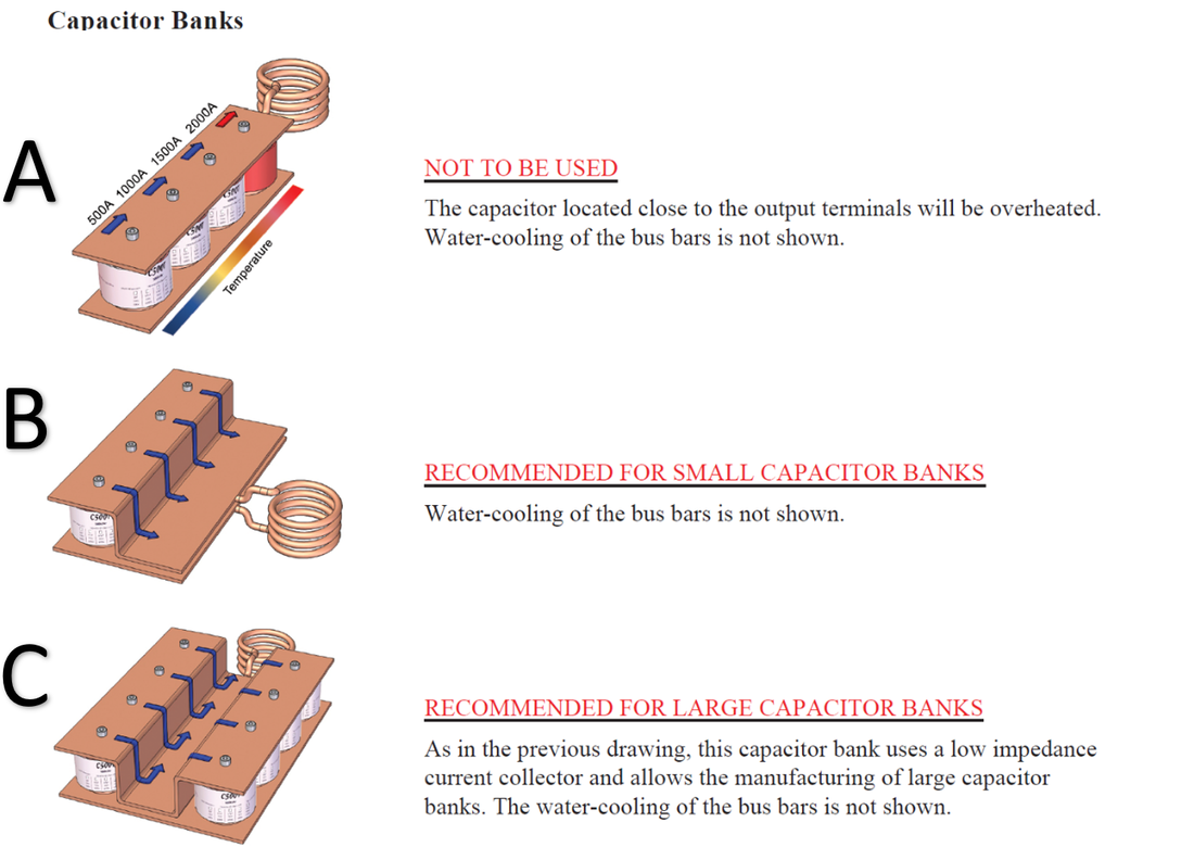
- Induction heating of capacitors. When several conduction-cooled capacitors are assembled between two bus bars, those located closest to the output terminals may experience induction heating. This situation should be avoided by mounting the capacitors as illustrated in diagram B or by building a low inductance path between the bus bars as illustrated in diagram C. The C-Cap technology overcomes this deficiency.
4. Stray inductance. Even when a capacitor bank is not connected directly to a work coil, it is good practice to avoid stray inductance in the circuit.
Inductance is proportional to the bus bars’ lengths, inversely proportional to their widths and inversely proportional to the distance between the
bus bars.
Inductance is proportional to the bus bars’ lengths, inversely proportional to their widths and inversely proportional to the distance between the
bus bars.
3. Capacitor Bank Losses
A capacitor bank consists of capacitors and connections between the capacitors and output terminals. Losses may be associated with either of these elements.
Capacitor losses. Losses in the capacitors are extremely low, generally about 5 x 10⁻⁴ x the reactive power.
Connection losses. In a properly constructed capacitor bank, connection losses will be approximately the same as the capacitor losses.
Total capacitor bank loss is equivalent to the sum of the capacitor losses and connection losses. As such, it generally totals about 10-3 of the reactive power.
4. Required Water Flow for Capacitor Bank Cooling
Polypropylene capacitors can safely run at temperatures of up to 90°C. The temperature gradient between the hottest points of the polypropylene element and the copper surface of Celem capacitors is 40-45°C. Therefore, external surfaces of the capacitors must not exceed 45°C. In practice, the cooling water temperature at the outlet of the cooling circuit should not exceed 40°C.
When the capacitor bank is cooled in series with the work coil, the losses of the work coil are at least ten times that of the capacitor bank. Therefore, the capacitor bank should be cooled first, followed by the work coil.
When the capacitor bank is cooled in series with the work coil, the losses of the work coil are at least ten times that of the capacitor bank. Therefore, the capacitor bank should be cooled first, followed by the work coil.


